When working with libGDX (or any other OpenGL based system), you will have to deal with various coordinate systems. This is because OpenGL abstracts away device dependent units, making it more convenient to target multiple devices and to focus on game logic. Sometimes you may need to convert between coordinate systems for which libGDX offers various methods.
It is crucial to understand in which coordinate system you are working. Otherwise it can be easy to get confused and to make assumptions which aren’t correct.
On this page the various coordinate systems are listed. It is highly recommended to first get familiar with the concept of Cartesian coordinate systems, which is the most widely used one.
- Touch coordinates
- Screen or image coordinates
- Pixmap and texture coordinates
- Normalized render coordinates
- Normalized texture (UV) coordinates
- World coordinates
- GUI/HUD coordinates
- Game coordinates
Touch coordinates
| Units | pixels |
| System | y-down |
| Type | integer (can't be fractional) |
| Range | (`0`, `0`) (upper left corner) to (`Gdx.graphics.getWidth()-1`, `Gdx.graphics.getHeight()-1`) (lower right corner) |
| Usage | touch/mouse coordinates |
| Dependence | device specific |
Starts at the upper left pixel of the (application portion of the) physical screen and has the size of the (application portion of the) physical screens width and height in pixels.
![]()
Each coordinate is an index in the 2D array of this grid, representing a physical pixel on the screen. Therefore these coordinates are always represented as integers, they can’t be fractional.
This coordinate system is based on the classic representation of the display, which is usually also closest to the device/OS specific implementation. If you’re familiar with canvas graphics or basic image editors, then you are probably already familiar with these coordinates. You might even lean towards using these as your default/favorite, which you shouldn’t.
Whenever working with mouse or touch coordinates, you’ll be using this coordinate system. You typically want to convert these coordinates as soon as possible to a more convenient coordinate system. E.g. the camera.unproject or viewport.unproject method let’s you convert them to world coordinates (see below).
Screen or image coordinates
| Units | pixels |
| System | y-up |
| Type | integer (can't be fractional) |
| Range | (`0`, `0`) (lower left corner) to (`Gdx.graphics.getWidth()-1`, `Gdx.graphics.getHeight()-1`) (upper right corner) |
| Usage | viewport, scissors and pixmap |
| Dependence | device/resource/asset specific |
This is OpenGL’s counterpart to touch coordinates; that is: it is used to specify (index) a pixel of the (portion of the) physical screen. It is also used as indexer for an image in memory. Likewise, these are integers, they can’t be fractional.
The only difference between touch and screen coordinates is that touch coordinates are y-down, while screen coordinates are y-up. Converting between them is therefore quite easy:
y = Gdx.graphics.getHeight() - 1 - y;
You typically use these coordinates to specify which portion of the screen to render onto. For example when calling glViewport, glScissor or manipulating a pixmap (see next). In the majority of use-cases you don’t need this coordinate system a lot, if any, and it should be isolated from your game logic and its coordinate system. The camera.project and viewport.project methods can be used to convert world units to screen coordinates.
Pixmap and texture coordinates
Pixmap coordinates are an exception. Pixmaps are commonly used to upload texture data. For example when loading a PNG image file to a texture, it is first decoded (uncompressed) to a Pixmap, which is the raw pixel data of the image, then it is copied to the GPU for use as texture. The texture can then be used to render to the screen. It is also possible to modify or create a pixmap by code, e.g. before uploading as texture data.
The “problem” with this is that OpenGL expects the texture data to be in image coordinates, which is y-up. However, most image formats store the image data comparable to touch coordinates, which is y-down. libGDX does not translate the image data between the two (which would involve copying the image line by line), instead it simply copies the data as is. This practically causes a Texture loaded from Pixmap to be up-side-down.
To compensate for this up-side-down texture, SpriteBatch flips the texture (UV) coordinates (see below) on the y axis when rendering. Likewise, fbx-conv has the option to flip texture coordinates on the y axis as well. However, when you use a texture which isn’t loaded from a pixmap, for example a Framebuffer, then this might cause that texture to appear up-side-down.
Normalized render coordinates
| Units | one |
| System | y-up |
| Type | floating point |
| Range | (`-1`, `-1`) (lower left corner) to (`+1`, `+1`) (upper right corner) |
| Usage | shaders |
| Dependence | none |
The above coordinate systems have one big issue in common: they are device specific. To solve that, OpenGL allows you to use a device independent coordinate system which is automatically mapped to screen coordinates when rendering. This coordinate system is normalized in the range [-1,-1] and [+1,+1] with (0,0) exactly in the center of the screen or framebuffer (the render target).
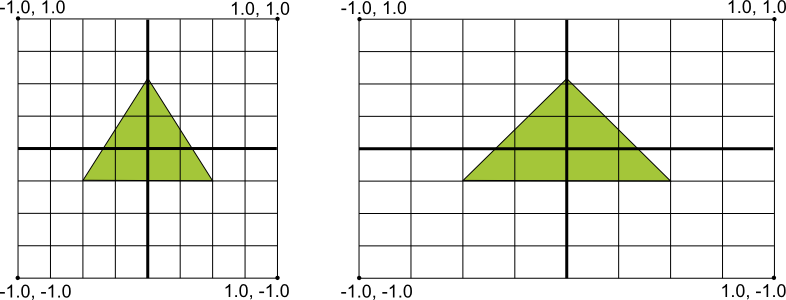
The vertex shader outputs (gl_Position) its coordinates in this coordinate system. But other than that, you should never have to use this coordinate system in a practical use-case. It is sometimes used in tutorials and such, though, to show the basics.
It might be worth to note that the normalization does not respect the aspect ratio. That is: the scale in the X direction does not have to match the scale in the Y direction. They are both within the range of -1 to +1, regardless aspect ratio. It is up to the application to decide how to deal with various aspect ratios (see world units, below).
The coordinates are floating point and no longer indexers. The device (GPU) will map these coordinates to the actual screen pixels using rasterisation. A good article (although targeting DirectX it also applies to OpenGL) for more information on that can be found here.
Normalized texture (UV) coordinates
| Units | one |
| System | y-up |
| Type | floating point |
| Range | (`0`, `0`) (lower left corner) to (`1`, `1`) (upper right corner) |
| Usage | shaders, mesh, texture region, sprite |
| Dependence | none |
Likewise to the normalized render coordinates, OpenGL also uses normalized texture coordinates. The only difference is that these ranges from [0,0] to [1,1]. Depending on the specified wrap function, values outside that range will be mapped within that range.
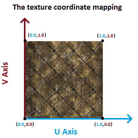
These coordinates are also called UV coordinates. In many use cases you don’t have to deal with them. Typically these values are stored in the mesh or TextureRegion.
The use of normalized texture coordinates is very important, because it makes them independent of the asset size. Or in other words: it allows you to replace your assets with a scaled down or scaled up version, without having to modify the UV coordinates. An example where this is used are mipmaps.
When rendering, the GPU converts the UV coordinates to a texel (texture pixel). This is called “texture sampling” and is based on the texture filtering.
World coordinates
| Units | application specific, e.g. [SI Units](https://en.wikipedia.org/wiki/International_System_of_Units) |
| System | application specific, but usually y-up |
| Type | typically floating point |
| Range | application specific |
| Usage | game logic |
| Dependence | game/application |
Typically, your game logic should use a coordinate system which best fits the game logic. It should not depend on device or asset size. For example, a commonly used unit is meters.
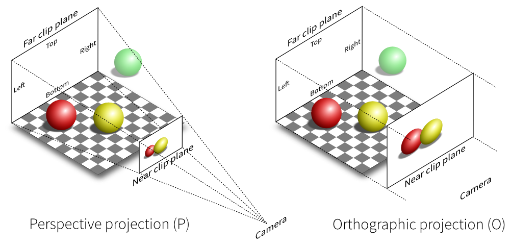
The world coordinates are converted, in the vertex shader, to normalized render coordinates. The Camera or Viewport is used to define the strategy on how to do that. For example, to maintain aspect ratio, black bars can be added. The camera is used to calculate the view matrix, which translates your world coordinates into coordinates relative to the camera, by taking in consideration the location and rotation of the camera. It also calculates the projection matrix, which converts the world coordinates to the normalized render coordinates in the range [-1,-1] to [+1,+1]. In 2D games, you mostly dont need the distinction between these two matrices and only need the combined transformation matrix instead. You can pass this matrix to the shader, for example, by calling spriteBatch.setProjectionMatrix(camera.combined);
You can have multiple camera’s or viewports and likewise, you can also have multiple world coordinate systems. A typical game has at least two of those, namely:
GUI/HUD coordinates
These are buttons, labels and such which are stationary and always visible on the screen. Often they involve rendering text. For example in Super Mario the clock is always visible in the upper right corner of the screen and does not move when mario moves in the game world.
Most commonly scene2d is used for the HUD, which means that you’d use a Viewport to define the coordinate system. This coordinates system is typically in a range that is close to the device resolution, to give the best results when rendering the font. These coordinates are called banana units. This camera is practically never moved or rotated, it sits stationary at a location so that the world coordinate (0, 0) is located at the bottom left corner of the screen.
Game coordinates
This is what suits best for your game and is used to implement game logic. It is good practice to keep the values around one for the best floating point precision. For example, your main character is 1.8 meter in height, the tree is 10 meter in height, etc. If you are making a galactic game where units and distance are very high, you might want to use e.g. kilometers instead.
The camera is used to look into your game world, just like it would when you use a video camera in the real world. The camera can be moved, rotated and scaled to display another portion of the world on the screen.